Tracking biscuit thickness in die casting on every shot provides a significant amount of information about process consistency and the root cause of casting quality problems.
Too much variation in either direction can indicate the casting is less dense, which would increase the probability of having, and finding porosity in the casting. Finding this scrap at the end of a complex process of casting, machining, and pressure testing is also very costly. Remelting good castings due to a misunderstanding of the data is also costly. As with any tool, for the most effective results, we need to understand how to apply it and the limitations (or assumptions).
Biscuit thickness is not actually measured in production because doing so accurately on every shot would be too costly.
- Instead, it is calculated using the difference between the starting position of the shot tip to the parting line and the total stroke length.
- If part of the biscuit is cut into the ejector side, this additional depth can be added to the parting line distance.
- Traditionally, the biscuit thickness is between 20 and 35 mm (~0.75” and 1.25”, more or less).
If the biscuit thickness calculation does not correspond to the actual measured biscuit thickness, always look at the assumptions first.
Assumptions
What factors can affect an inaccurate calculation for the biscuit thickness? We’re assuming the plunger tip is returning to the exact same position every time and is stationary until the start shot signal occurs. Both factors affect the position of the plunger tip at the start of the calculation.
- Check the return position of the tip. Is it possible to temporarily add a magnetic base and a travel indicator to the plunger rod for confirming the return position? Does it return to the same place or is there variation?
- Also, confirm there is no plunger drift. This is the forward motion of the tip prior to the start of injection. That means the hydraulic system has some leakage and allows the tip to creep forward before the monitor receives the shot start signal. Any forward drift reduces the calculated travel resulting in an incorrectly thin biscuit calculation. The actual biscuit will be the same nominal thickness. Plunger drift can also be checked while the travel indicator is installed.
- It also doesn’t hurt to double check the distance to the parting line because overlooking the most simple details can lead to a substantial amount of wasted effort.
When the calculation is accurate and there is also variation in the thickness, where does it come from?
Inconsistent Shot Volume
If the biscuit thickness calculation correlates to the actual measured biscuit thickness, check for variation in the amount of molten metal delivered into the shot sleeve. There is a certain amount of natural variation related to the fluctuating level of molten metal in the holding furnace.
A higher level allows more volume into the ladle which creates a thicker biscuit. A thicker biscuit takes longer to solidify and can explode or be too soft to extract properly.
A lower level in the holding furnace allows less volume which creates a thin biscuit. A thin biscuit can solidify too quickly, reducing the effectiveness of intensification, and is also difficult for a robot to grasp properly.
In both cases, differences in the molten metal volume can affect the location of the liquid metal at critical stages of the process.
This creates variation in the trajectory of molten metal during filling and can produce casting quality issues.
- More volume means the melt is farther ahead in the runner system when the tip begins the transition from slow to fast shot.
- Less volume means the melt is farther behind in the runner at the same plunger tip position.
That means the liquid metal will enter the cavity differently, changing the filling pattern and possibly creating a quality problem.
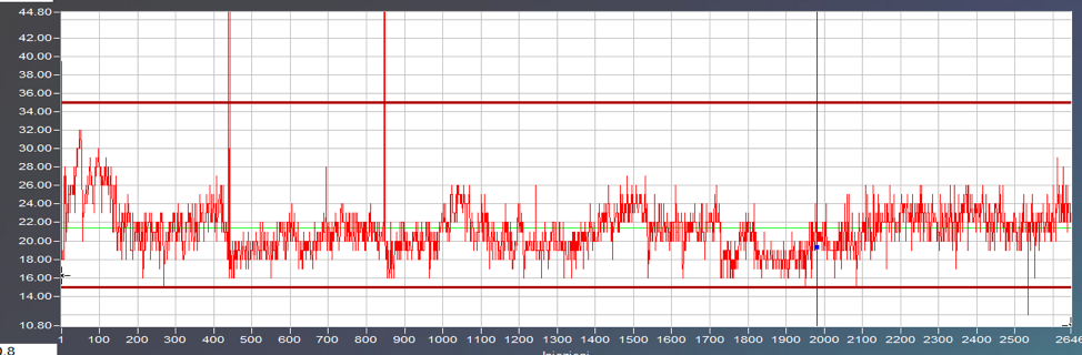
The graph below displays the biscuit thickness variation for 2,600 production cycles. The thin green line defines the setpoint value 21.5 mm (~0.85”) and the heavy red lines indicate the minimum and maximum limits at 15.0 and 35.0 mm (~0.60” and 1.38”). Note, this range is far greater than what is normally acceptable. Traditionally, a biscuit thickness would be 25mm +/- 5.0mm (1.00” +/- 0.20” but a better tolerance would be 25mm +/- 2.5mm (1.00” +/- 0.10”). The graph displays an interesting sinusoidal pattern which corresponds to the normal fluctuation of metal level in the holding furnace. Biscuit thickness tends to have a certain amount of natural variation due to this fluctuation.
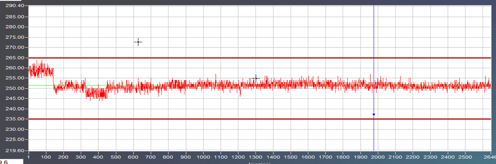
Meanwhile, the second graph below displays the effective intensification pressure over the same 2,600 production cycles. Again, the thin green line represents the set point pressure at 251 bar (~3,640 psi) and the heavy red lines at 235 and 265 bar (~3,400 and 3,840 psi) are the upper and lower limits. We can see that after the first 4 hours of set up, the effective intensification pressure is very stable at +/- 4 bar.

Since biscuit thickness naturally has some variation, it is important to track other parameters such as effective intensification pressure.
For example, if the furnace level is steadily dropping and nearing its lowest level, but just before the furnace was refilled the biscuit thickness of an individual shot increased (but was still below the upper limit), what might have happened? The biscuit was supposed to be thin but instead was thick.
- It’s possible the effective intensification pressure wasn’t achieved, resulting in a casting with greater porosity.
- If using only biscuit thickness as an indicator, the system would allow a bad casting into production.
- However, when effective intensification pressure is also used as an indicator, the bad part can still be identified and removed from the production stream.
Other Variables
When there is a positive correlation between scrap (porosity) and biscuit thickness, and real biscuit thickness variation indeed exists, there are several other variables to consider.
Intensification rise time, pressure, and duration; If the applied pressure vs time curve during intensification is inconsistent, the biscuit may freeze before enough melt is forced into the casting cavity. This is also known as effective intensification pressure mentioned previously.
Cold metal; If the molten metal delivered into the cavity is too cold (either from the holding furnace or due to delay before the start of the shot), it can lead to faster solidification and less molten metal transferred into the casting cavity.
Die flashing; At the end of the shot, if “low impact” is not being used and the clamping force of the machine is exceeded, molten metal will force the die open allowing metal out of the cavity and in between the parting surfaces on the die. This can produce a thin biscuit as well as less metal inside the casting cavity. Both can result in greater porosity.
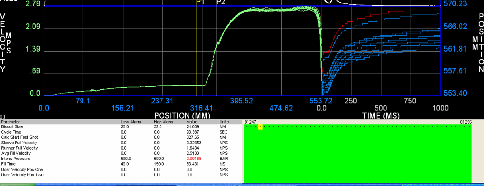
Notice the parameter “Biscuit size” is a tracked variable in the above image. The yellow dot represents 1 out of 50 shots which had enough variation to generate a warning but not an alarm.
The biscuit thickness calculation is stored with the rest of the shot data for every casting made. If there are any quality problems with the castings, using traceability, this parameter can be evaluated to determine if there is any correlation between biscuit thickness variation and casting quality. If there is, limits for warnings and alarms can be set up to check this parameter every cycle to automatically sort the suspect castings or warning the operator of a potential problem.
While biscuit thickness is not the only critical variable, it can be used effectively to understand casting quality and, if nothing else, an improved metal delivery schedule to refill the holding furnaces in the plant.

Comments are closed